1 General
2 Running conditions
3 Technical parameter
4 Main configuration
1 General
Self-propelled Module Transporter is a special-purpose vehicle with a hydraulically operated lifting and lowering facility and is suitable for transporting heavy loads, such as prefabricated sections within a shipyard. The transporter can drive under pedestal-supported loads, lift the load by means of the lifting system, transfer it to any desired location, and set down the load, without the aid of a crane or other lifting equipment. It can be controlled by one man only. The design incorporates all the latest safety precautions to ensure efficient operation.
1.1. Name
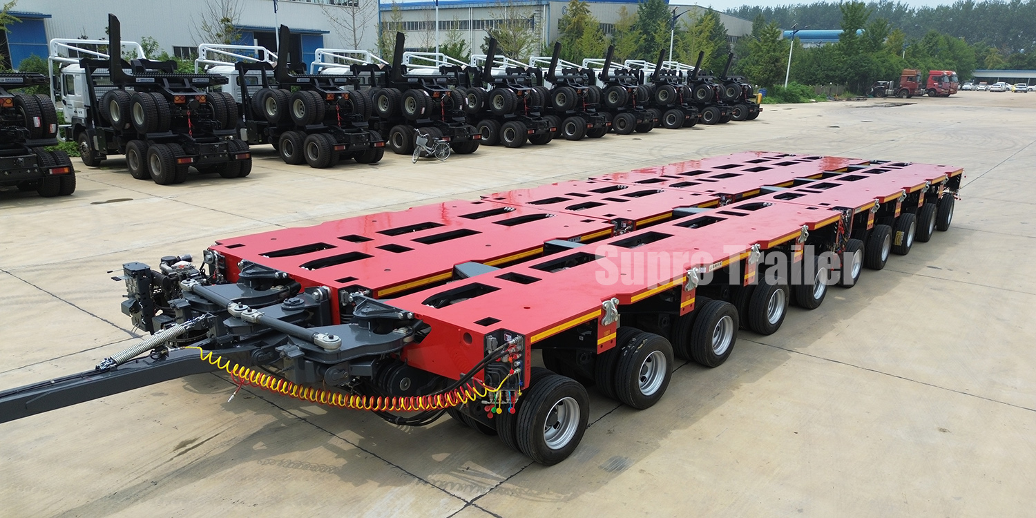
SUPRO -Self-propelled Module Transporter
1.2. Qty.
The quality of main device and accessories is shown in table 1 and table 2.
13. Works scope
It is a turnkey project. According to the requirement of the agreement, tenderer offers one set of quality product. The project includes design, manufacture, pre-installation debugging, pre-acceptance before leaving workshop, packing, delivery, unloading, inspection, installation debugging, test-drive, final acceptance and the operating training after service.
4. Project contents
This project is composed of two sets of 6-axle self-propelled module transporter including 2 sets Power Pack Unit (PPU), 2 sets of 6-axle module unit without power. And there is another set of PPU for spare. The general arrangement is shown in figure 1.
2 Running conditions
Ambient temperature: -25℃~55℃.
Relative humidity: ≦92%,
Wind scale: ≦6
Ground condition: Bituminous pavement or concrete road (rolling drag as per 0.018-0.020) or pressed earth road (rolling drag as per 0.025-0.035)
3 Technical parameter
The configuration of 6-axle self-propelled module transporter is shown in drawing 1, 1 set of PPU + 1 set of 6-axle module unit.

3.1 The general technical parameters of 6-axle module unit
Axle---------------------------------------------------------------6
Length of platform(mm)--------------------------------9000
Width of platform(mm)----------------------------------3000
Height of platform(mm)----------------------------------980~1650
Max. total mass(kg)---------------------------------------- 204,000
Curb weight(kg)-------------------------------------------------24,000
Rated loading weight(kg)--------------------------------180,000
Load per axle(kg)-------------------------------------------34,000
Load per suspension(kg)--------------------------------17,000
Number of drive axle------------------------------------------2
Qty. of drive suspension--------------------------------------4
Speed(unload Km/h)--------------------------------------8
Speed(full load Km/h)-------------------------------------3
Gradient ability(%)-----------------------------------------9
Hydraulic compensation(mm)-------------------------670
Wheel angle(°)----------------------------------------------±110
Tractive force(kN)-----------------------------------------360
Braking force(kN)------------------------------------------348
Wheelbase(mm)-------------------------------------------1500
Wheel track(mm)------------------------------------------1800
Turning radius(mm)--------------------------------------4847
Qty. of tyre------------------------------------------------------48
Tyre specification---------------------------------------------215/75 R17.5
Electric system(V)-------------------------------------------28
Remote controller--------------------------------------------Radio
Suspension type----------------------------------------------Hydraulic 3 or 4 points supporting
Steering type---------------------------------------------------Electrical control hydraulic combined multi-steering
Frame type------------------------------------------------------Box-shaped structure
Braking system------------------------------------------------Dual-tube diaphragm spring braking system
membrane /spring brake
3.2 Parameters of PPU
L(mm)×W(mm)×H(mm)----------------------2750×2980×850
Lifting angle(°)------------------------------------------6
Dead load(kg)------------------------------------------5000
Manufacturer of engine----------------------------------CUMMINS
Engine type-------------------------------------------------ISDe 180 30
Engine power--------------------------------------------- (kW/ rpm) 132/ 2500
Emission standard---------------------------------------GB/III
Fuel tank volume(l)----------------------------------280
Hydraulic oil volume(l)------------------------------600
Max. operating pressure of driving system(bar)------420
Max. operating pressure of steering system(bar)-----350
4 Main configuration
4.1 PPU
PPU is composed of engine, transfer case, filter, heat radiator, inter-cooler, oil cooler, variable pump, fuel tank, hydraulic oil tank, battery, etc. Steering and elevating electrical control hydraulic valves are also arranged in PPU.
4.2 Frame
Frame is the mainly part of loading part and designed as per the most dangerous loading condition with safety coefficient 1.3. The main bearing parts (such as beam and flat plate) adapt box-shaped beam structure and welded by high quality plate (HG785), yield strength: 685MPa. A detachable cover plate is installed on the surface of transporter.
4.3 Hydraulic system
Hydraulic system is composed of driving, steering, suspension system. Oil pump variable adapts hydraulic variable technique which can prove driving speed effectively. Constant-voltage control is used in steering oil pump. Under high pressure, there is lower displacement with high response characteristic. With independence hydraulic radiator system, radiator system oil pump is installed on engine to make sure the reliability of radiating when there is no displacement to improve oil pump life.
4.4 Hydraulic suspension
Suspension system is hydraulic suspension to keep the loading platform horizontal when driving on convex-concave pavement. Supporting system adapts hydraulic suspension system which can form 4 points (see drawing 2) or 3 points(seen drawing3) supporting.
Axles and frames are connected through suspension and the height can be adjusted. Hydraulic suspension is consists of suspension, swinging arm, suspension cylinder, gyrating device, etc, which is installed on frame crossbeam. Wheel axle is arranged on the top of swinging arm. Suspensions and wheel axles will elevate and swing to make sure all the wheel axles are loaded balanced.
Altitude transducers are arranged on the four corners of the vehicle for each transporter. Elect-proportional multi-valve is standard configuration for PPU which can realize the synchronism elevating of one transporter or more of them.
4.5 Electrical multi-steering system
This system is consists of steering oil pump, multi-valve, steering motor, wormwheel and worm-steering system, angle transducer, controller, etc. (see drawing 4)


4.6 Steering structure
One angle transducer is equipped for each suspension. When slide operating handle, remote controller sends a steering signal and controllers work out each suspension’s theory angle according to the set steering mode. Then controller work out the valve opening through comparing the angle transducer feedback signal and the theory value. At last, hydraulic motor drives suspension to steer to the right position.
There are seven steering modes: crab driving, normal driving, front-axle steering, rear-axle steering, oblique driving, 90°driving, circle driving at one point. And other driving modes can be set according to customer’s requirement. Steering modes of tandem are the same. (see drawing 5 and 6). If steering deviation is over 8°, steering system will be locked and transporter can move anymore or there is a alarm single.


a. Crab driving b. Normal driving


c. Front- axle driving d. Rear- axle driving


e. Oblique driving f. 90° driving


g. Circle driving at one point
4.7 Video of the SPMT steering
4.8 Operation and micro-electric control system
While driving, the direction handle inputs steering and leveling signals those are switch values.
Adopting the computer micro-electric auto-control system (control schematic diagram will be offered), all the multi-mode could be realized through controller. The micro-electric control system adopts CAN bus communication, each action or power element is equipped with one simulating control board. Any control and instrument signals are input master control box through multi-core cable and then processed by the center computer to control, adjust and drive corresponding elements. The working conditions of the whole vehicle can be simulated by the screen in the control cabinet and displayed in digital, which is not only intuitionistic but also maneuverable.
4.9 Anti-skid control
For the rotational speed sensor is mounted on each driving axle, the micro-electric system monitors the actual slip ratio real-time during driving. If the slip ratio of any driving wheel exceeds the setting value, the micro-electric system will send a signal at once to reduce the motor displacement of the driving wheel. The up steps are to ensure other driving wheels’ traction, fulfill the anti-skid control and fulfill the motor protection.
4.10 Brake system
The brake system adapts shoe brake and is equipped a air-compressor. And the double-cavity spring braking air chamber realizes its function through spring energy and diaphragm brake air chamber. When the spring air chamber is deflated by the manual control valve, the spring can do the parking brake. If there is something wrong with the air-compressor, the spring can fulfill the brake function alone.
There are two sets of air-compressor system. One is service braking system and the other is independent parking brake system.
Service brake: While braking, the compressed air enters into the diaphragm cylinder directly from the air reservoir to brake.
Parking brake: Parking brake can be done through the spring force, (even if the pipeline has a breakdown).
4.11 Electric control system
The self-propelled module transporter’s rated voltage is 28V, with two 180AH batteries. The electric control and monitor instruments of the PPU adopt the color liquid crystal display.
The micro-control system adopts Bosch Rexroth special controllers for the engineering truck RC6-9 and its expanded module to make sure its reliability and stability. The communications between controllers and the controllers to displayers all adopt the CAN bus.
In addition with the common operation and monitor function, the electric control system also has the following display functions.
Instrument indication: speed, engine rotational speed, oil pressure, oil temperature, water temperature and the air pressure of the brake system;
Alarm lamps: high pressure turning filter alarm lamp, preheating control indicator lamp, oil suction and return filter driving system alarm lamp, air pressure brake alarm lamp, oil return filter alarm lamp, battery charge indicator lamp, parking brake indicator, fuel low alarm indicator, engine oil pressure alarm indicator, refrigerant temperature alarm indicator, hydraulic oil level alarm lamp, air filter alarm lamp.
Lighting: turning, backing, alarming, outline lamp, head light.
The transporter is equipped with the control box and all the control components are set in the control box. The marks of the line number (terminal No.) on the vehicle should accordance with drawings, and all kinds of marks should be firmly and reliable. All the components of the vehicle should be available, and accordance with the drawings.
Configuration of electric control system: special controllers for the engineering truck, LCD, encoder, pressure sensor and main cable are imported and the safety standard of the electron device is IP65. Common electric components and cables adopt first-rate joint venture products and military industrial products. The electric-control boxes and electric components’ satisfy standard is IP 55.
4.12 Remote controller
There are radio remote controller and emergency steering remote controller. Radio remote controller can achieve the function of acceleration, lifting, lowering, forward, backward, turning left and right, ignition, burn-out, emergent parking, setting of the steering mode, information monitor, etc
The emergent steering remote controller can achieve steering function of each wheel independently. If steering deviation is over 8°, the emergent steering remote controller can be used to steer the corresponding wheel to the initial position.
4.13 Connection
Each modular transporter is not connected. The hydraulic joint pin is used in the longitudinal connection, and the transverse connecting device is used in the transverse connection
Each modular has its own control system, which can achieve its functions such as self-steering synchronization. Through the CAN bus information, the modules can also achieve the coordinate synchronization. During communication, one modular is defined as master unit, the other modules receive the order such as steering, driving, and braking from the master unit.


4.14 Painting
After shot-cleaning, the surface of the steel structure reaches SA2.5 grade. The thickness of the application and paint film must be up to the national standard (more than 150μm). The well-known brand paint is used in painting. Most of the top-coat is R03. All of the small accessories adopt galvanization.